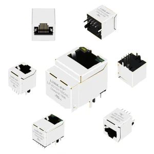
Explore our curated selection of high-performance vertical entry RJ45 female sockets. Engineered for space-restricted, high-density system configurations.
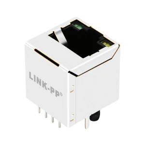
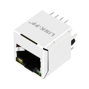
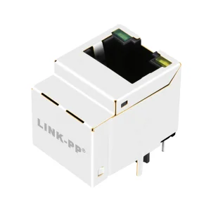
In modern electronic design, the orientation of data interfaces plays a crucial role in optimizing PCB real estate, thermals, and mechanical structural integrity. A vertical RJ45 connector, also known as a top-entry or 180-degree RJ45 jack, mounts perpendicular to the printed circuit board (PCB) surface. This differs significantly from standard right-angle (90-degree) connectors that project horizontally from the PCB edges.
Engineers leverage vertical female RJ45 sockets when the panel layout demands routing Ethernet patch cables directly from the top or when stacked side-by-side configurations are blocked by adjacent layout components. By shifting the insertion axis vertically, design footprints are substantially reduced, allowing multi-layer architectures to support denser channel counts.
Vertical design structures present unique design variables. The internal leads inside a vertical RJ45 connector run straight down to the PCB pins, minimizing the signal transit distance. In high-frequency operations, such as Category 6 (Cat6) and Category 6A (Cat6A) Gigabit transmission, even millimeter deviations in trace length can induce electromagnetic interference (EMI) or crosstalk. Vertical alignment helps achieve symmetrical pin configuration, reducing signal propagation skew and optimizing differential pair balances.
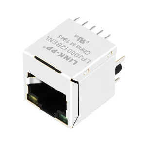
Reduces surface layout area by up to 40% compared to traditional horizontal modular jacks, facilitating higher port densities.
Perpendicular SMT/THT terminals achieve superior solder coplanarity, which prevents signal loss in automated pick-and-place processes.
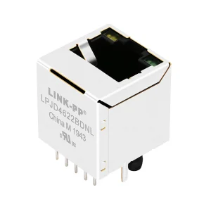
Advanced internal metal shielding shields critical transmission lines against high-frequency environmental noise.
Procurement engineers must look beyond simple mechanical fitment when selecting vertical RJ45 female connectors. Signal transmission speed, Power over Ethernet (PoE) capacity, internal magnetic isolation, and environmental sealing are crucial variables that dictate final system reliability.
| Parameter Category | Cat 3 Unshielded | Cat 5e With Magnetics | Cat 6 / Cat 6A Shielded | Cat 7 Ruggedized IP67 |
|---|---|---|---|---|
| Frequency Range | 16 MHz | 100 MHz | 250 MHz / 500 MHz | 600 MHz |
| Typical Data Rate | 10 Mbps | 1 Gbps (1000Base-T) | 1 Gbps / 10 Gbps (10GBase-T) | 10 Gbps+ |
| Magnetics Integration | Discrete (No Integrated Magnetics) | Integrated (MagJack/Fastjacks) | Optional Integrated / Discrete | External high-frequency isolation |
| LED Options | Typically No LEDs | Bi-color green/yellow available | High-brightness SMD LEDs built-in | Visual indicator optional |
| PoE Compatibility | Non-compatible | PoE / PoE+ (up to 30W) | PoE++ (up to 90W) | Custom industrial power configs |
| Primary Application | Legacy telephony / low-speed control | Enterprise switches, IoT gateways | Data center servers, high-speed PHYs | Outdoor industrial IoT, harsh environments |
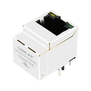
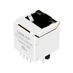
Ethernet physical layer (PHY) chips require external isolation transformers and common mode chokes to isolate electrical noise and protect circuits from static surges. Standard vertical RJ45 jacks (non-magnetic, such as the SS-7188VS-A-NF-50 or 87547-4111clf) require these components to be laid out discretely on the motherboard.
Conversely, magnetic RJ45 connectors (like the LJ-H17S4I-00-F or the SI-46004-F series) house these coils, resistors, and capacitors directly inside the metal housing. This integrated approach, often referred to as a MagJack, significantly simplifies board design, reduces EMI footprint, and guarantees impedence matching, speeding up time-to-market.
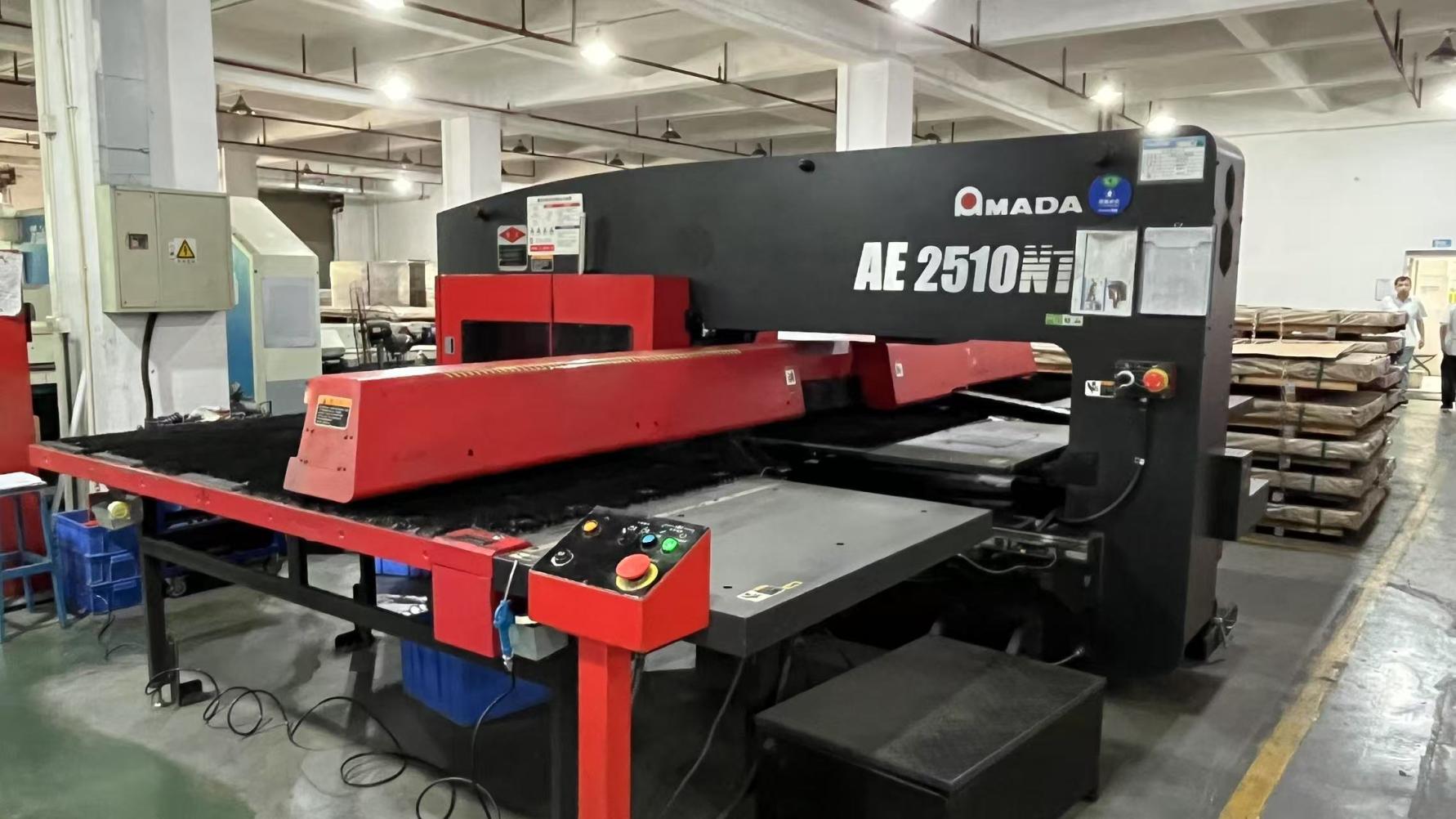
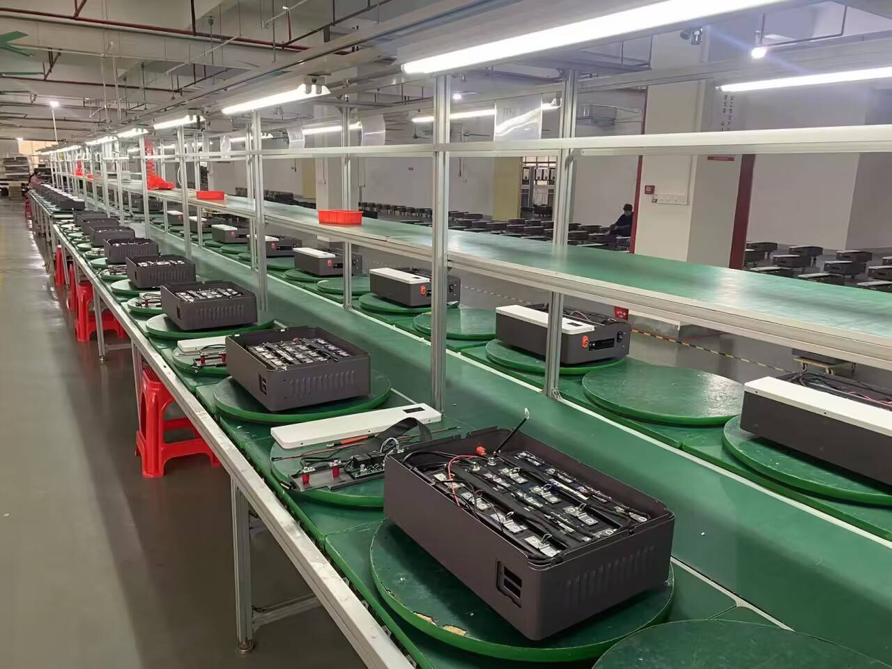
The global electronics supply chain relies heavily on Chinese manufacturing hubs for passive component sourcing. This reliance is driven by specialized technical capabilities and efficient vertical integration. From copper alloy stamping and high-speed electroplating (specifying up to 50u" gold contact surfaces) to insert molding and automated optical inspection, Chinese factories deliver high precision at scale.
Accumulated technical expertise in optical communications and copper interconnect solutions.
Extensive trade experience servicing North America, Europe, Southeast Asia, and the Middle East.
High-volume export footprint reflecting strong global partnerships and capacity reliability.
Rigorous testing protocols including AOI, eye diagram analysis, and temperature cycling.
Founded in 2016, OptiLinker Optoelectronics Co., Ltd. (OptiLinker) operates under the brand name OptiLinker (www.optilinkertrans.com). While specializing in high-speed optical transceivers for data centers and telecom applications, OptiLinker relies on its deep connection to the regional electronic component ecosystem to coordinate macro network connectivity solutions.
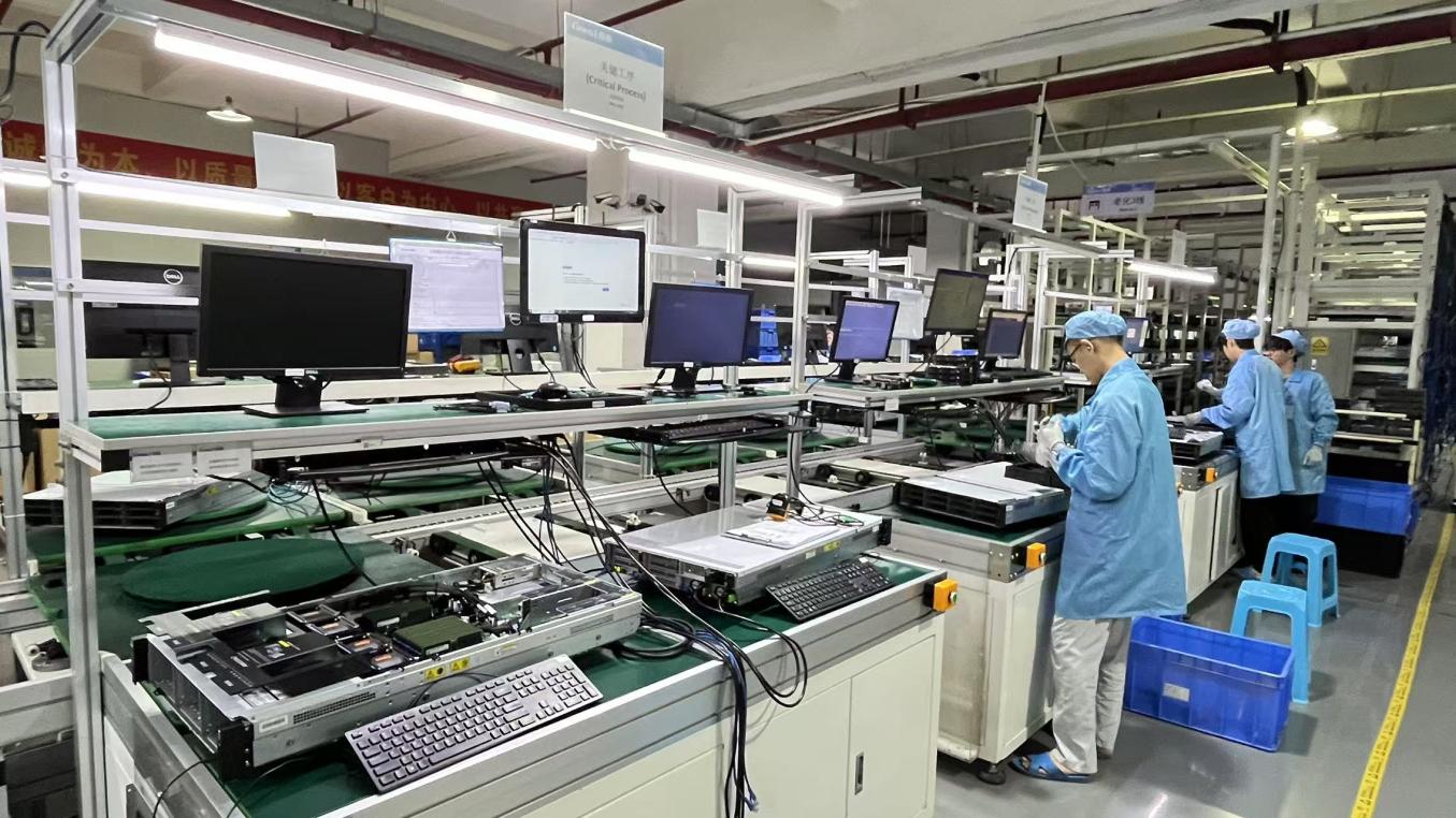
Operating from a modern production facility of approximately 320m², the company has integrated robust manufacturing practices, including AOI automated optical inspection, BER (Bit Error Rate) testing, eye diagram analysis, and high/low temperature cycling tests. This guarantees that copper and optical components withstand extreme, demanding environments. Supported by a network of 850 supply partners, an engineering team of 60 professionals, and 35 dedicated QC specialists, OptiLinker launched approximately 120 new products last year, demonstrating rapid adaptation to evolving industry demands.
Ethernet interfaces serve as the backbone for diverse hardware ecosystems. The integration of vertical RJ45 jacks is critical across several key sectors:
Modern server blades utilize high density architectures. Vertical RJ45 connectors allow for top-entry cable access, ensuring structural isolation from hot-swappable cooling paths. Selecting high-frequency Cat6a/Cat7 components reduces insertion loss and crosstalk in dense racks.
Factory equipment requires highly stable connections to withstand continuous mechanical vibration. Ruggedized vertical RJ45 jacks with multi-point grounding pins secure connections to DIN-rail mounting platforms and automation controllers, keeping assembly lines online.
Under the IEEE 802.3bt (PoE++) standard, up to 90W of power can be delivered over CAT cables. Modern vertical jacks are engineered to handle high current loads without thermal buildup, powering PoE LED luminaires and advanced smart-building sensor networks.
Procurement departments and hardware design leaders must establish rigorous inspection standards to verify performance before initiating volume production. The checklist below highlights key criteria for qualifying a new RJ45 supplier:
The contact interface requires high-grade phosphor bronze with electroplated gold overlay. For high-cycle applications (greater than 750 mating cycles), specify a gold plating thickness of 30u" to 50u". This prevents oxidation and contact resistance drift in humid or corrosive industrial environments.
With standard lead-free wave and reflow soldering processes exceeding peak temperatures of 260°C, the connector housing must be made of high-temperature thermoplastic (e.g., LCP or Nylon 9T). This prevents structural warping during thermal processing.
Environmental certifications are mandatory for compliance with global electronics import regulations. Sourcing agents must verify that suppliers provide up-to-date SGS test reports verifying the absence of lead, cadmium, and polybrominated biphenyls.
For automated surface-mount assembly (SMT), connectors should be sourced in Tape & Reel packaging with integrated polyimide pick-up caps. For through-hole reflow (THR) or standard manual wave assembly, tray packaging is typically preferred to prevent pin deformation during transit.
Technical answers to common questions about selecting and integrating vertical RJ45 connectors.
Review our high-speed, waterproof, and PoE-compatible vertical connectors, designed for demanding networking infrastructure applications.