Explore our top-tier active and passive interfacing components engineered for zero-loss signal splitting, high-speed optical routing, and ruggedized industrial Ethernet terminations.
In contemporary telecommunications and enterprise networking, the mechanism of distributing physical layer signals requires a strict focus on signal integrity, electromagnetic interference (EMI) containment, and impedance matching. As a premier hub for hardware development, identifying the right Ethernet splitter manufacturer involves auditing their baseline knowledge of transmission line theory, high-frequency design principles, and mechanical durability.
Passive Ethernet splitters rely strictly on standard pin remapping configurations to route two separate 10/100 Base-T channels over a single physical 8-conductor Category-rated cable. This approach exploits the fact that Fast Ethernet (100Base-TX) utilizes only two differential pairs (transmit on pins 1 & 2; receive on pins 3 & 6), leaving the remaining four pins vacant. An active switch, conversely, manages traffic dynamically at Layer 2 of the OSI model, storing and forwarding packets across separate collision domains.
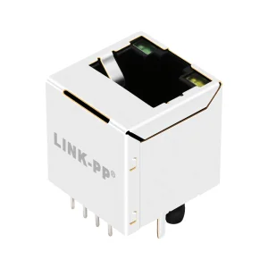
Maintaining a nominal differential impedance of 100 ohms (+/- 15%) across all interconnects is vital for minimizing return loss. Improper design leads to severe Near-End Crosstalk (NEXT) and Far-End Crosstalk (FEXT) when high-frequency data streams interact. Leading manufacturers employ state-of-the-art EMI shielding cages, magnetic integration, and high-frequency printed circuit board (PCB) routing patterns to isolate these lines from external radiative noise.
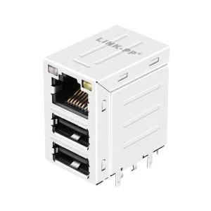
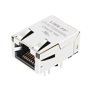
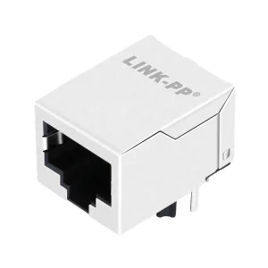
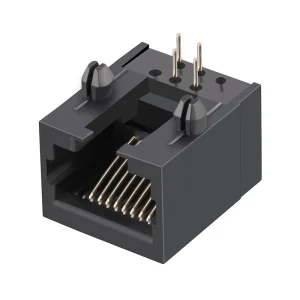
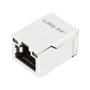
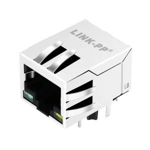
Modern Ethernet architecture relies heavily on integrated connector modules (ICMs or Magjacks). By integrating isolation transformers and common mode chokes directly inside the RJ45 physical housing, manufacturers prevent DC bias current loops and protect sensitive PHY transceiver chips from common-mode voltage surges and ESD events.
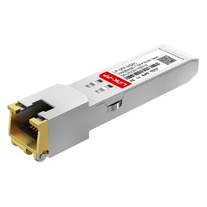
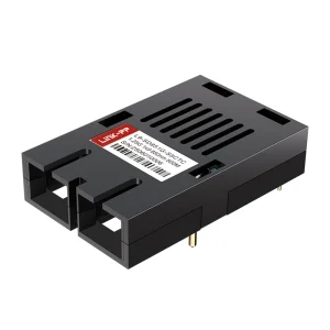
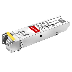
As industries undergo accelerated digitalization, the demand for compact, cost-effective physical layer deployment solutions has grown exponentially. According to recent industrial networking data, copper-based Ethernet architectures still support over 65% of local edge connections, even as fiber optic backbones expand to meet high-bandwidth requirements. This dynamic creates a critical need for components that link fiber endpoints to copper interfaces (such as SFP-to-RJ45 transceivers and media converters).
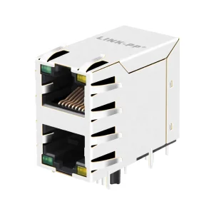
Firms seeking to increase workstation density without routing additional Cat6A lines through structural walls rely on multi-channel physical interfaces and optimized splitting units to split single wall outlets into dual active feeds. This reduces deployment costs by up to 45% in commercial spaces.
Industrial Internet of Things (IIoT) architectures require localized data nodes. In these rugged spaces, robust EMI-shielded RJ45 connections and specialized magnetic connectors guarantee that electrical noise from high-voltage machinery does not disrupt packet transmission lines.
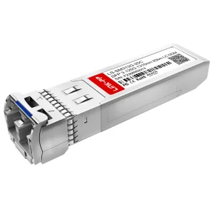
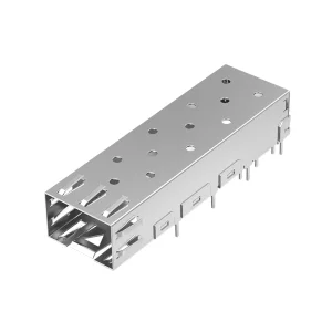
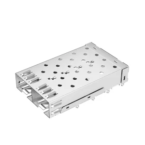
The transition from pure copper to hybrid networks highlights the value of components like SFP cages and multi-rate SFP modules. These allow operators to run fiber lines to local cabinets and distribute local signals via shielded RJ45 lines to edge devices.
Integrating Ethernet splitting components and magnetic jacks requires adapting to diverse regional environments and architectural regulations. Below are typical scenarios that global system integrators face:
In North American buildings, strict NEC (National Electrical Code) rules govern cable installations in plenum spaces. System integrators use passive, highly fire-resistant structural splitting devices paired with CMP-rated cabling. This allows them to scale network drops in historical buildings without violating local fire codes.
Under strict European EMCD (Electromagnetic Compatibility Directive) parameters, factories in Germany and Northern Europe require fully shielded, high-frequency RJ45 components. Integrating connectors with internal magnetics ensures compliance with EN 55032 standard emissions limits in dense production environments.
Deployments in telecommunication nodes across Southeast Asia face intense thermal cycling and high relative humidity. Using components that pass environmental tests (like thermal cycling and salt mist testing) is essential to prevent micro-corrosion on gold-plated contact pins.
As global supply chains navigate changing macroeconomic conditions, China’s electronics manufacturing ecosystems remain resilient. This stability is driven by deep component-level vertical integration, highly automated optical assembly processes, and skilled labor.
A prime example of this industrial capability is OptiLinker Optoelectronics Co., Ltd. (OptiLinker). Established in 2016, OptiLinker functions as a professional optical transceiver and physical connection solution provider under the brand OptiLinker (www.optilinkertrans.com). They supply high-speed optical communication modules and magnetic connectors for global data centers and telecom applications.
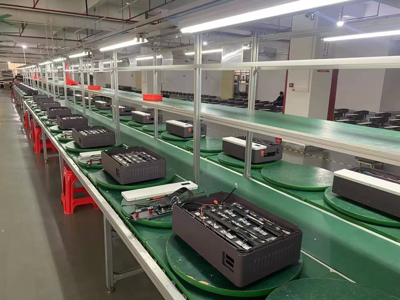
OptiLinker operates a modern production facility designed for high-precision optical alignment and cleanroom packaging. Drawing on over 12 years of industry experience and 8 years of export experience, the company has shipped over USD 12 million in high-performance networking products annually to customers in North America, Europe, Southeast Asia, and the Middle East.
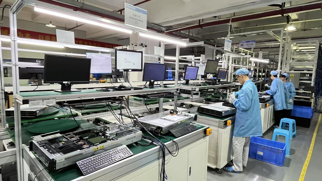
Reliability in telecommunication components is non-negotiable. An Ethernet connection failure can lead to expensive operational downtime. OptiLinker achieves zero-defect manufacturing by implementing rigorous testing frameworks run by 35 dedicated QC professionals.
Every substrate, magnetic coil, housing material, and IC undergoes 100% incoming physical inspection to verify electrical shielding and geometric tolerances before entering the cleanroom.
Automated Optical Inspection systems scan component placement on the PCB. They detect soldering bridging, cold joints, and alignment deviations at the micron level.
High-speed transceivers undergo real-world traffic testing, verifying BER and analyze eye diagrams to ensure signal margin and low jitter.
Components endure high and low temperature cycling (-40°C to +85°C) to ensure physical integrity and stable operation in harsh field installations.
Supported by an active R&D group of 60 experienced optical and mechanical engineers, the company develops custom configurations, including custom wavelength tunings, specific transmission distances, custom firmware coding, and device compatibility programming. Demonstrating high agility, OptiLinker launched 120 new products last year to meet the evolving needs of telecom operators and data center administrators.
Ethernet interfaces are evolving beyond Gigabit transmission speeds. The industry is currently preparing for multi-gigabit edge networking, Single Pair Ethernet (SPE), and advanced Power-over-Ethernet (PoE++). Understanding these trends helps system integrators source future-proof components.
SPE uses just a single pair of copper wires to transmit data and power (PoDL - Power over Data Line) up to 1000 meters. This development will simplify IoT device connections, reducing cabling weight and space in automotive and industrial control systems.
As edge devices require more power, RJ45 connectors must support 90W PoE (IEEE 802.3bt Type 4) without saturating the internal magnetic transformers. This requires advanced magnetic cores and superior heat dissipation designs.
For data center links exceeding 100Gbps, traditional copper faces physical attenuation limits. The future lies in hybrid systems where optical engines sit close to the processing units, relying on high-density SFP/QSFP cage assemblies and fiber interfaces.
Below is the remainder of our technical catalog, featuring custom SFP assemblies, integrated modular jacks, and high-frequency communication modules designed for professional networks.
Get answers to critical engineering and sourcing questions about Ethernet connectors, splitters, and transmission limits.